| You should already know that the
roadwheel comes off. |
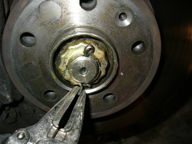
| Straighten out and remove cotter pin from
center of the wheel. Throw it away, but only after you have used
it to select its replacement. |
 |
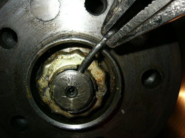 |
| Remove the protective ring. |
|
 |
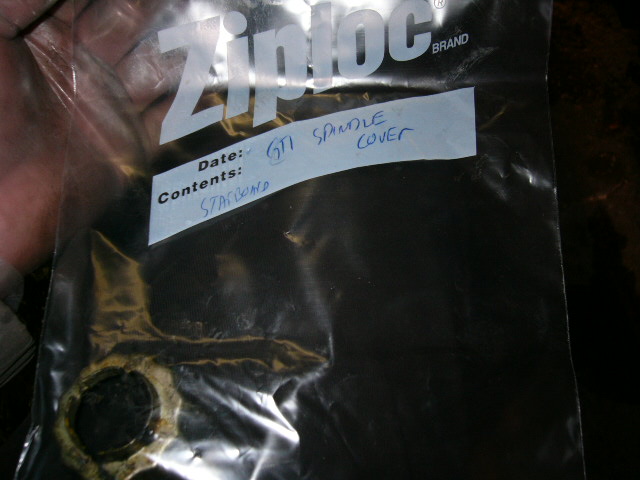
| And put it in a plastic bag that you have
labeled. EVERYTHING removed from a car goes in a plastic bag
with a label. Never move on to the next step until you have
catalogued the part just removed. |
 |
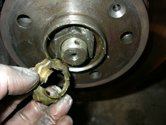
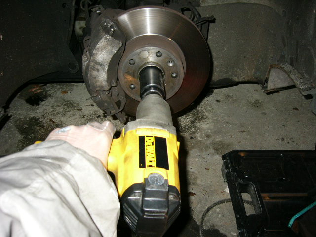
| Lots of people seemed to have problems
getting the hub bolt off. Not surprising given the factory
specifies 250 foot-pounds of torque at installation. Use an impact wrench & let it beat the
shit out of the nut until it's loose. Took about 5 seconds of
pounding until it came loose. It's a 35mm socket. You have
to have a functional parking brake, or the other wheel on the ground,
with the transmission in gear. Otherwise the wrench will just
turn the axle and brake disc. |
 |
| Next, remove the locknut at the lower
balljoint
 |
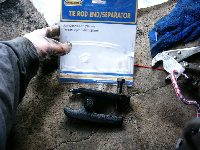
| This is the tool I used to separate the balljoint.
This tool only works on the Series I cars. A different tool is
necessary for the Series II. |
|
 |
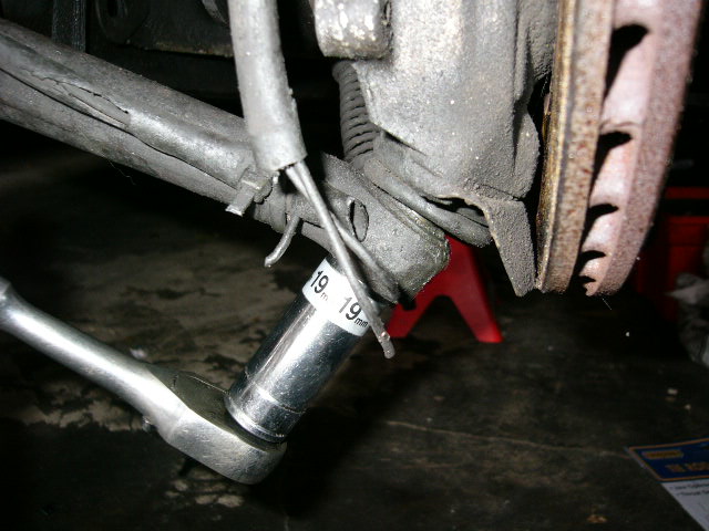
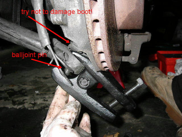
| The tool in place. Yeah, I know all the
tools say 'protect your eyes,' but this time you really need to
heed the warnings. You will put a LOT of
pressure on the tool to cause it to loosen the joint.
Normally this pressure will work to press the joint through the hole.
But if the joint is stuck, the tool could come off instead. When the
pin disconnects, it sounds like a shotgun. No, I am not
pushing the screw with my foot. I was careful not to damage
the rubber boot at the base of the lower balljoint. A 19mm socket will
turn the screw. This side came loose after about 5-6 turns of
the wrench.. |
 |
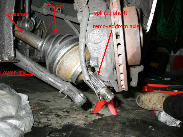
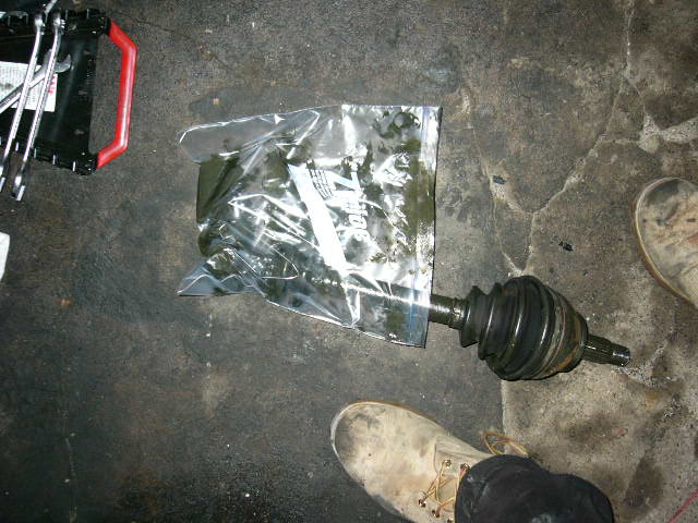
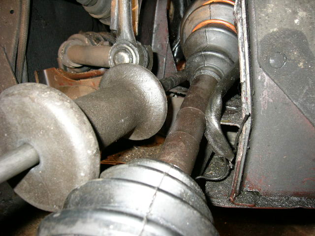
| Once the lower balljoint pin is free, I
turned the axle/wheel assembly such that the driveshaft came loose.
I gave the axle a few taps from the outside to loosen the driveshaft.
In this picture, the driveshaft has been removed from the axle. The
wires hanging in front of the splined section are for the brake pad
warning light. Someone cut them.
Digression:
I have yet to see a car where these wires have not been cut.
They are cut because Citroen routed the wires along the lower arm to
the caliper. To disconnect the lower arm, the wires must be
disconnected and unraveled from the caliper, something that requires
loosening several more screws. Or you can cut the wire.
Guess what most shops do? This is a prime example of one
engineer not talking to another, or the design team not looking at
what happens to their work out in the real world. I'm sure
there is a reason for routing the wires along the lower arm that is
complètement logique, probably relating to less wear or stress on
the wire. But in practice, this design forces
additional work to separate the lower arm from the pivot. If the
wiring were routed along the upper arm, a balljoint or driveshaft job
could be done without removing the wires. The guy who designed
the wiring never looked at the tasks involved in a balljoint job or a
driveshaft job. I see examples of this type of bullshit
engineering time and again on these cars.
end of digression
Use rope to hold the pivot
assembly out of your way. . |
 |
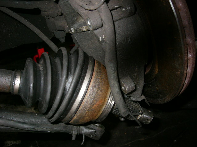
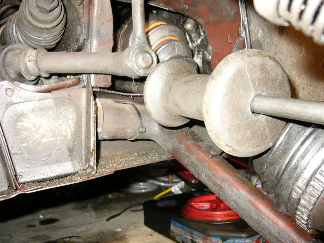
| Another view of the driveshaft removed from the axle. |
 |
| You are now ready to pull the
driveshafts. The shop manuals advise you to disconnect the
anti-roll bar connections. This is not necessary, and is just a waste
of time for now. You can get the driveshaft out without this
step; replacing it might be difficult. Leave it in place
for now. Now that the driveshaft is free from the outside axle,
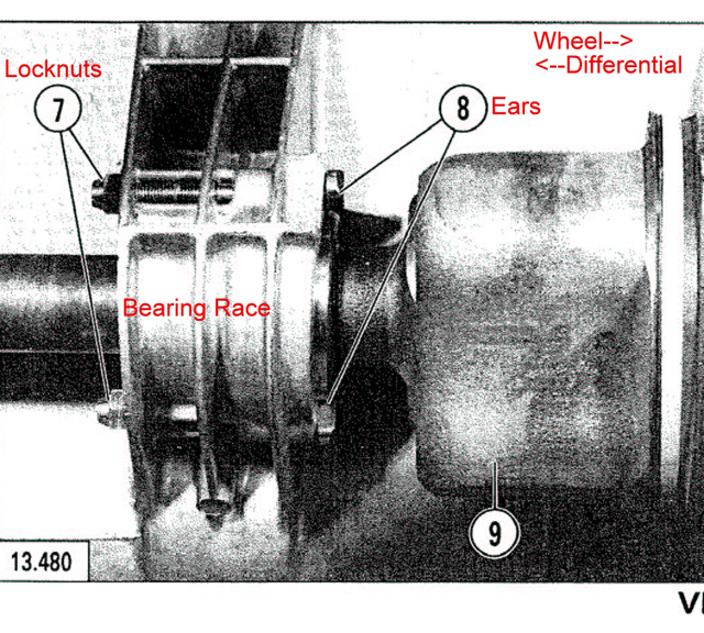
it's time to pull the shaft from the car. The port (left)
side shaft attaches directly at the differential. The starboard
side driveshaft passes through an intermediate bearing in a race
attached to the engine crankcase. This bearing is held in
place with two long screws with a head that has an 'ear' on one side
(8 on the photo below). The 'ears' hold the bearing in place.
The long screws are anchored with locknuts (7 in the photo) that are
on the differential side of the bearing race. The easiest way to
reach these two nuts is from underneath. A stubby ratchet wrench
is indispensable!! Get the socket set in place and work it until it
feels really loose. This means the long bolts are loose.
Feel around on the other side of the race and you will find them.
|
| Here's the bearing race: |
 |
| On the 25GTi, the right-side shaft
came out with a firm tug, once I had loosened the bolts on the bearing
race.
But what if the driveshaft won't come out easily? The
quickest and easiest way to keep your project moving is to cut the
boot. The only thing holding the triax
together is the rubber boot. Without the boot, the entire axle
would just slide out. So, I did an episiotomy on the boot.
What's an
episiotomy? Ask any woman who has had a kid & then run
because she will either throw things at you or kick you or something
like that. |
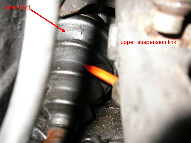 |
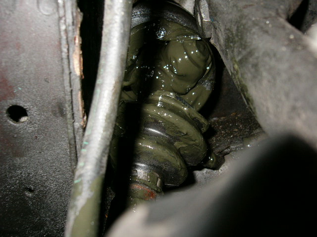
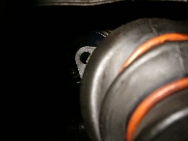
| Another shot, better focus. A sharp eye will
note that I disconnected the upper link from the suspension cylinder.
Disconnecting the cylinder will make the suspension / axle
assembly easy to move, but this is certainly not necessary to remove
the driveshaft. |
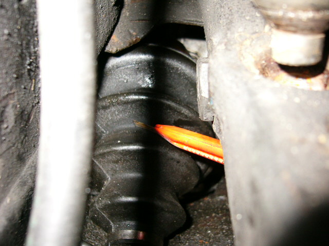 |
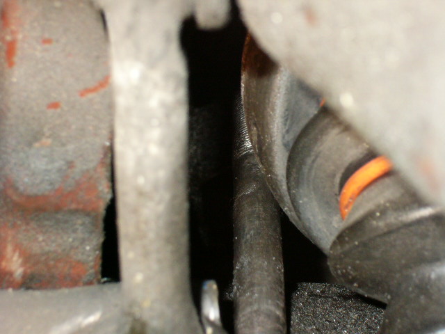
| In this view the boot is cut about 270°.
It is possible to rotate the driveshaft around so that you can keep
cutting the boot from the top. The triax is partially exposed - the
grease inside is visible. |
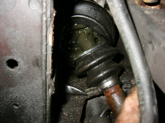 |
| In this view, one of the three triax arms is free from
the carrier. |
 |
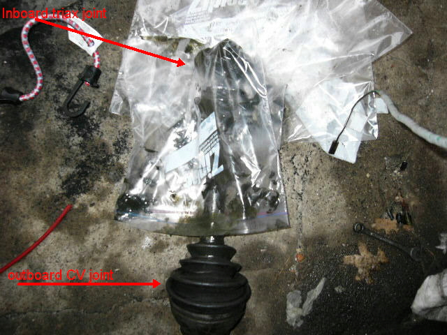
| Once the triax joint is removed from the housing,
put it in a plastic bag. The triax must not get any dirt in it.
Dirt and grit will ruin the bearings. Label the bag BEFORE you
move on to the other side of the car. |
 |
| |
 |
| |
| If you don't want to do the episiotomy, there is this
tool: |
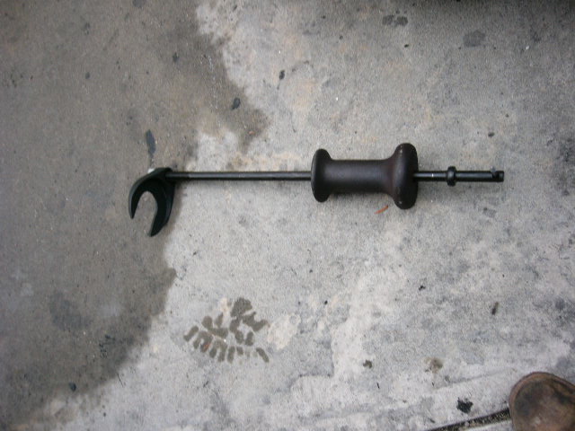 |
| It's called a driveshaft puller.
Most parts catalogs list it as a tool to pull driveshafts for a Ford
Mondeo.
First, separate the hook from the shaft.
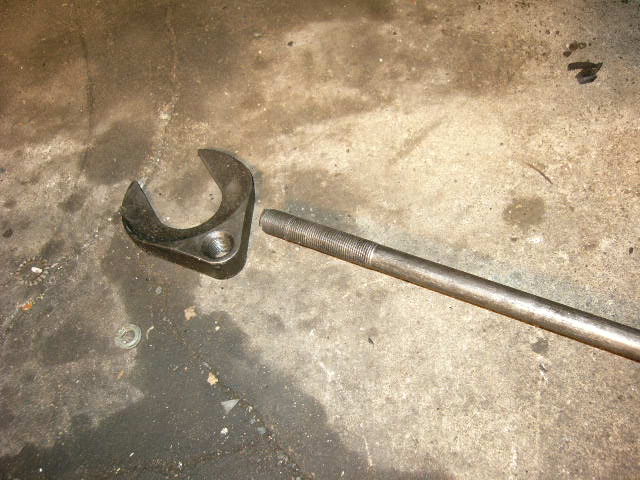
The triax case is larger than the indented portion on
the hook; use the flat side against the back of the case. Make
sure the flat side is towards you.
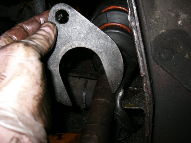
You will need to reach up through the opening under the car, in the
crossmember just aft of the motor, and position the hook next to the
inboard side of the triax case. Sorry, no photos from
under the car. In this photo the threaded hole in the hook is
visible just past the triax case. That's the rubber boot of the
triax visible in the front.
Threading the rod back into the hook is easier than it would seem.
It helps if you can rest the bar or at least the slide hammer weight
on something while you are turning the rod. I held the hook with
my left hand through the hole in the lower crossmember and turned the
rod with my right hand. Make your life much easier by
giving the threads a good cleaning and douse everything with WD-40 or
some other very light oil. Note that I did not
disassemble the anti-roll bar link, as advised by the shop manual.
It's possible to do this job with the link in place.
Now, just pound the hell out of the slide hammer and the shaft will
eventually come out. If you reach up though the hole in the
crossmember, you can feel the position of the bearing as it
moves out of the race. The shaft will move more easily if the
driveshaft is aligned with the hole in the differential. On the
right side, this is ensured by the
bearing race that is part of the lower crankcase for about the
first inch of outward travel. Once the bearing is free of
the race, the entire driveshaft will be at an angle to the
differential hole, and thus more difficult to remove. I
would support the outside end of the drive shaft by putting it back
into the hole in the wheel hub.
|
| Now,
taking it apart and cleaning it. |