| The following is a an explanation of the functions a
the Weber Carburetor, the 34 DMTR. I have made the description
to introduce principles of the general functioning of Weber
carbs. There are other functions not discussed here, but can be
found elsewhere. I'd recommend the Haynes book. |
| The DMTR is a compound progressive carburetor.
Compound because it has two barrels, progressive because the throttles
open progressively, not simultaneously. It has three circuits:
Idle/low speed, primary and secondary. These three circuits
correspond to the motor's operating range: idle / low speed,
partial throttle, and full throttle. |
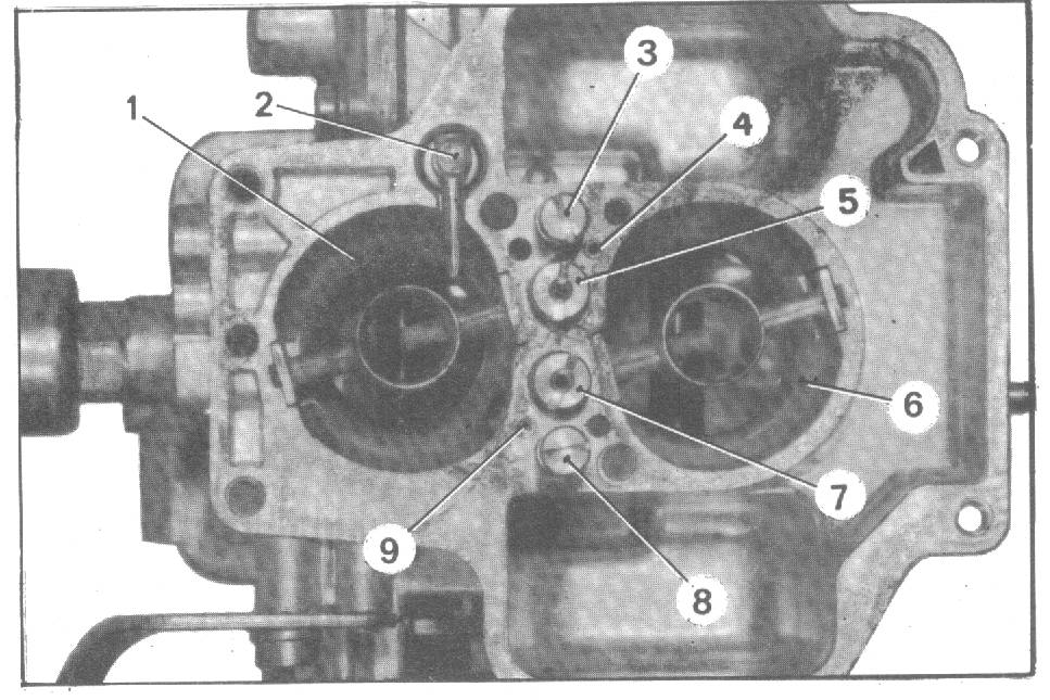
| Here's a scan of a photo of the deck of the 34DMTR.
The float bowl cover has been removed, so the float bowl is visible,
surrounding the round barrel on the right. Labels for
3,4,5,6,7,& 8 are in the float bowl. |
 |
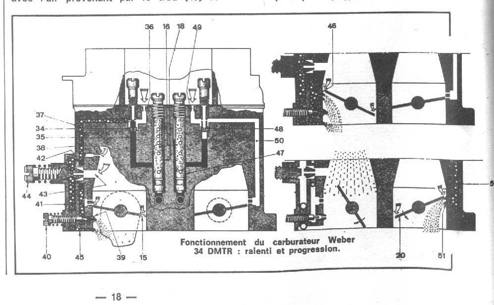
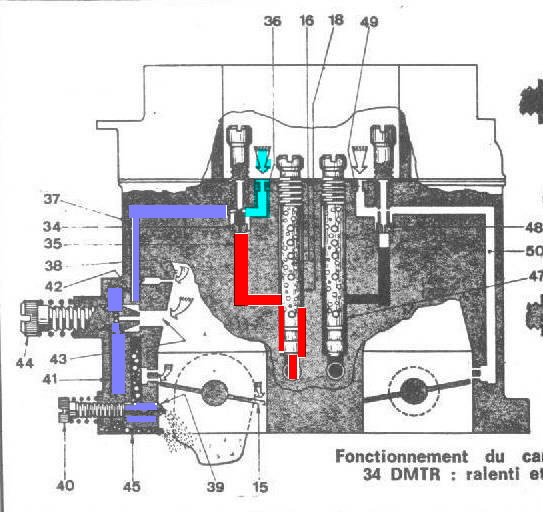
| This first diagram shows the carburetor in cross
section; looking from the right. This is the same
orientation as the photo above. The screws on the left side of
the image are on the back. It shows the idle / progression
circuits in action. The full figure is at idle, the close-up at
the upper right is a low speed, the close up at lower right is at
part-throttle. If you look at throttle plate in the left side
barrel, you will see that the plate is turning clockwise to open the
passage.
|
| Here's what happens when the engine is at idle, the
accelerator pedal at its stops. At idle, the throttle
plate is almost, but not entirely closed. There is a very small
gap between the throttle plate and the wall of the carb barrel.
This gap creates a venturi effect, an area of low pressure.
It's important to understand the venturi effect, since it is the
basis of the Weber's functioning. Effectively, if you move
air through a tube, and suddenly that tube gets smaller, the air moves
faster through the smaller part, and the pressure drops. It is
the drop in pressure that is important. If you have a low
pressure area and a high pressure area, fluid (in this case gasoline)
moves from the high pressure area to the low pressure area.
The gasoline in the carburetor is stored in a bowl that is exposed to
atmospheric pressure, 14 pounds per square inch, or 1Bar.
The pressure at the small part of the venturi is less than 1 Bar.
So, the higher air pressure of 1Bar pushes the fuel towards the low
pressure area in the venturi.
Anyway, there is a little gap between the throttle plate and the
wall of the barrel. So, the air moves a lot faster at this
point, and the pressure drops. At
this gap Weber has located a small hole that is the end point of the
idle circuit (# 39 in the drawing below, with the red arrow) |
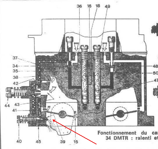 |
The hole at #39 receives a mixture of
fuel and
air. Why the mixture of fuel and air? Fuel by itself would
flow too quickly, and would be difficult to regulate. Mixing the
fuel with air slows its passage through the circuit. Weber calls
this fuel 'emulsified'. Air enters
through a hole in the deck of the carburetor (#36 in the
drawing immediately above and #4 in the photo at the top ). The mixture
is determined by the screw just to the left of hole #36. It is
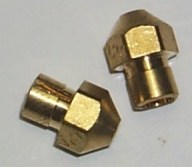
labled in the top photo as #3. At the
base of the screw is a "jet".
 The jet is a machined metal tube,
closed at one end with a single hole in the end or the side. There are slots
or holes in the sides of the tube. The hole is immersed in
gasoline,
and the gasoline is exposed to the air
through the slots in the tube. This air is at atmospheric
pressure. The fuel is at atmospheric pressure also, as the float
bowl is vented to the
atmosphere. The pressure at the venturi is less than
atmospheric, so the mixture of fuel and air
is pushed through the circuit (37, 41,
45) to the hole in the barrel(#39 in the drawing, #1 in the photo). The screw # 40
regulates the amount of emulsified fuel that is fed to the engine.
This screw adjusts the idle speed. The jet is a machined metal tube,
closed at one end with a single hole in the end or the side. There are slots
or holes in the sides of the tube. The hole is immersed in
gasoline,
and the gasoline is exposed to the air
through the slots in the tube. This air is at atmospheric
pressure. The fuel is at atmospheric pressure also, as the float
bowl is vented to the
atmosphere. The pressure at the venturi is less than
atmospheric, so the mixture of fuel and air
is pushed through the circuit (37, 41,
45) to the hole in the barrel(#39 in the drawing, #1 in the photo). The screw # 40
regulates the amount of emulsified fuel that is fed to the engine.
This screw adjusts the idle speed. |
 |
| Here's a closer view of the throttle plate
area as the accelerator starts opening. Push on the accelerator, the throttle plate opens a
little, and the venturi effect at the lowest hole diminishes.
The area of low pressure moves up in the barrel to the spot of minimum
gap between the plate and the barrel wall.
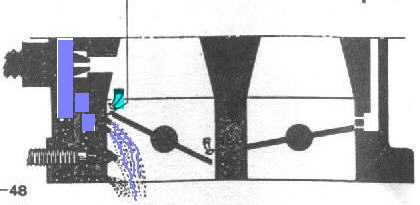
Sure enough, Weber put a hole there too, to provide a smooth
transition in fuel flow as the throttle is opened. Screw #
44 regulates this amount of emulsified fuel to the motor. |
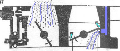
| When the throttle is opened further, the
venturi effect at the primary barrel wall diminishes. There is
no more pressure differential at the edge of the primary throttle to
pull emulsified fuel into the barrel. There is enough air moving
through the primary barrel to bring fuel through the main venturi
(more on this later) At a certain point, usually when the
primary throttle is about 2/3 open, the throttle on the second barrel
(# 6 in the photo) starts to open. The same procedure happens here as happened on
the primary throttle. A venturi is created at the edge of the
throttle plate, and this venturi pulls emulsified fuel through a
strategically located hole in the second barrel wall. This
follows passage 48 & 50 in the numbered diagram above. In
the drawing, #39 points to the air supply. In the photo, #8
points to the jet for this circuit and #9 points to the hole that
supplies air to this circuit. These are analogous to #3 and #4
for the primary circuit |
 |
| Here's another cross section of the carburetor. I
flipped the image to make it less confusing. Primary
barrel on the left and secondary barrel on the right. It shows the carb
at full throttle. |
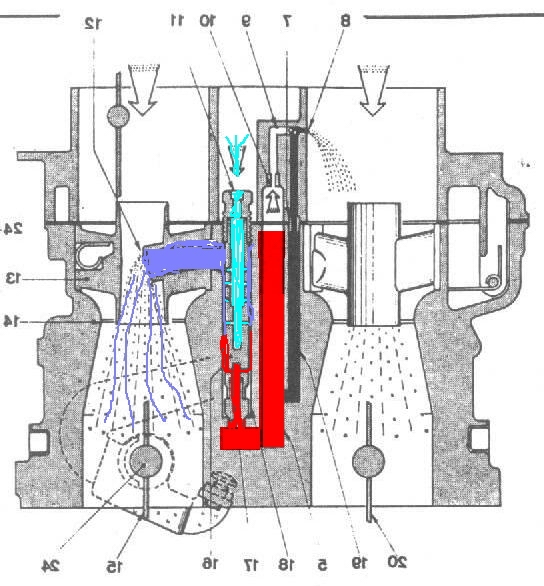 |
| The red is the fuel, the
blue is air at atmospheric
pressure, purple is emulsified fuel. Note first that
the level of the fuel is even with the top of the venturi (#12 in the
drawing).
This is important. If the venturi were higher, the pressure
differential between the venturi and the fuel would be too great.
The fuel would have to be pulled up against gravity. If the venturi were too
low, then fuel would spill out into the intake manifold.
Fuel is mixed with air in a sleeve / cylindrical chamber #16.
This chamber is connected directly to the venturi #12. A
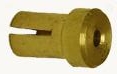
Main Jet (18)

 is
immersed in fuel. It has a hole bored through it to allow a
certain amount of fuel to pass. The corona of the main jet blocks fuel
from passing into the sleeve. Fuel can pass only through the
hole. The jet is attached to the end of an Emulsion
Tube is
immersed in fuel. It has a hole bored through it to allow a
certain amount of fuel to pass. The corona of the main jet blocks fuel
from passing into the sleeve. Fuel can pass only through the
hole. The jet is attached to the end of an Emulsion
Tube 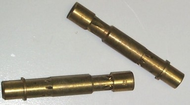 . The emulsion tube is hollow, with holes machined
into the sides. The machined holes allow a certain amount
of fuel/air mixture to pass from the inside outwards to be carried out
to the venturi. At the top of the tube is
another removable fitting, the Air Jet
. The emulsion tube is hollow, with holes machined
into the sides. The machined holes allow a certain amount
of fuel/air mixture to pass from the inside outwards to be carried out
to the venturi. At the top of the tube is
another removable fitting, the Air Jet
 . In the top
photo, the air jet for the primary circuit is #5, the air jet for the
secondary circuit is #7. The special machining
of this hole
allows a fixed amount of air to pass. Fuel comes up
into the bottom of the emulsion tube, air comes in from the top of the
emulsion tube, the two are mixed inside the tube, and pass through the
holes in the side to the venturi. . In the top
photo, the air jet for the primary circuit is #5, the air jet for the
secondary circuit is #7. The special machining
of this hole
allows a fixed amount of air to pass. Fuel comes up
into the bottom of the emulsion tube, air comes in from the top of the
emulsion tube, the two are mixed inside the tube, and pass through the
holes in the side to the venturi.
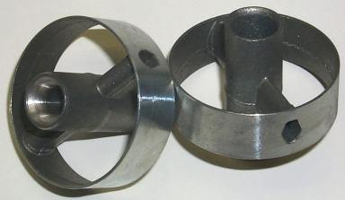 The venturi
is a tube inside a metal ring. The metal ring fits inside the
carb barrel. You can see the venturis suspended in the center of
the carb barrels in the top photo. The tube is suspended on a crossbar. One of
the arms of the crossbar is hollow, and is connected to the sleeve
holding the emulsion tube. The emulsified fuel exits the
tube through the holes in the side, into the sleeve, and then on out
to the crosspiece of the venturi. The cylinder in the center of
the venturi is a low-pressure zone. This low pressure pulls the
emulsified fuel through the passages. The venturi is designed so
that the low-pressure zone exists only when a lot of air is moving
through. At lower air volumes, such as at idle, there is no
vacuum differential. The venturi
is a tube inside a metal ring. The metal ring fits inside the
carb barrel. You can see the venturis suspended in the center of
the carb barrels in the top photo. The tube is suspended on a crossbar. One of
the arms of the crossbar is hollow, and is connected to the sleeve
holding the emulsion tube. The emulsified fuel exits the
tube through the holes in the side, into the sleeve, and then on out
to the crosspiece of the venturi. The cylinder in the center of
the venturi is a low-pressure zone. This low pressure pulls the
emulsified fuel through the passages. The venturi is designed so
that the low-pressure zone exists only when a lot of air is moving
through. At lower air volumes, such as at idle, there is no
vacuum differential. |
| |
| I mentioned earlier that I admired the elegance of
the Weber carburetors. This is a system that
provides properly metered fuel at idle, low throttle, part throttle,
and full throttle. The only moving part is the shaft of the
throttle plates, and these are moving parts already on the motor.
All the metering and mixing is done by differences in air pressure.
No additional moving parts are necessary to accomplish this task.
Another very nice thing about the Weber design is the range of
potential calibrations available. All the jets,
emulsion tubes, air bleeds, and venturis come in various calibrations.
The jets and tubes can be accessed from the top of the carb, and
removed with a screwdriver. Note in the top photo, items
#3,5,7 & 8 are cut to accommodate a screwdriver. The carb need not be
disassembled to change these parts. So, the motor
can be tuned for a wide range of operating conditions, all with the
same carburetor. The main criticism of Weber carbs is their
vulnerability to clogging. Having dealt with this personally
several times, I can understand the critique. The clogging
usually occurs on the primary air jet, (#5 in the photo & #11 in the
drawing immediately above) The primary emulsion tube
gets filled with junk, and air & fuel cannot mix and pass to the
venturi. This usually happens with before any clogging of the
low-speed/idle circuit. So, the car idles OK and runs fine at
low speeds, but stumbles and dies on acceleration. It's on
acceleration that the primary circuit becomes active. Engine
speed increases, the throttle lets more air in, but the primary
circuit is not allowing the proper amount of fuel to pass. So
now, there is not enough fuel to burn the air, and the motor stumbles
and stalls. Delightful in city driving.
Here's how I try to resolve the problem. |
| |
|