|
There are two systems to return LHM back to the reservoir:
the high-volume and the low-volume. The high-volume system
returns LHM that has been used for a function, or is surplus.
The low-volume system collects fluid that seeps from the components
and ducts it back to the reservoir. This seepage is intentional,
as it lubricates the metal parts. For example, the suspension
cylinders are two metal tubes, one inside the other. A very thin
layer of LHM between the tubes allows them to slide freely. This
LHM is caught by the rubber bellows and works its way back to the
reservoir.
Gravity does most of the work of returning fluid in the
low-volume system; residual HP accomplishes this task in the
high-volume system.
There are two low-volume systems: one that collects leaks from all
four suspension cylinder boots, the steering box and the steering
rack.
|
| LHM is used not only as a medium to
convey pressure, it is also used as a lubricant. Many of the
parts (suspension cylinders, height correctors) are two pieces of
metal sliding against one another. The LHM creates a lubricating
layer between the pieces of metal. Some of the LHM leaks from
these parts. This is normal and expected, as the LHM
carries away pieces of metal, sediment and rubber.
Just about all the hydraulic components have a small connection to
convey this LHM to the reservoir. |
| Over time the return lines get stained
and clogged with rubber, etc. |
 |
 |
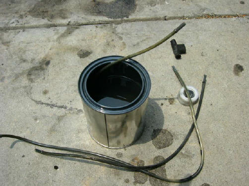
| I gave a good mineral spirit bath to the
translucent tubes and π-connectors. I call them
π-connectors because that's what they look like. |
 |
|
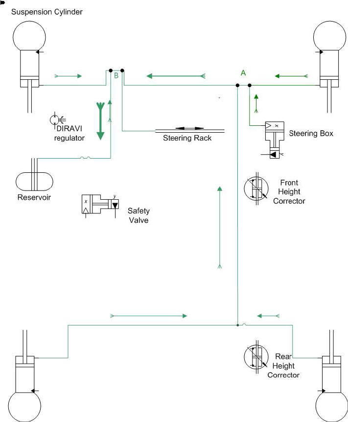
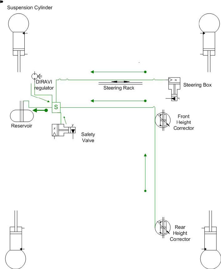
Here is my diagram of the leak lines from the suspension
boots, the steering box and the steering rack. Note junction points
"A" and "B", which are in the photos below. |
 |
| |
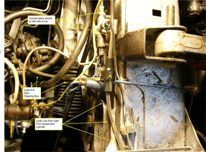
| Junction point "A" just aft of the crossmember behind
the engine. In this photo, the line from the front and rear
height correctors is not connected to the Pi-junction. |
 |
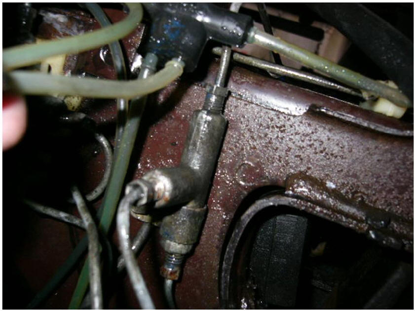
| Another view of junction point "A".
This was taken when I was cleaning the dirt and grease from the engine
compartment. |
 |
| Junction point "B" on the crossmember
behind the engine, left side of the car (under the spare tire). |
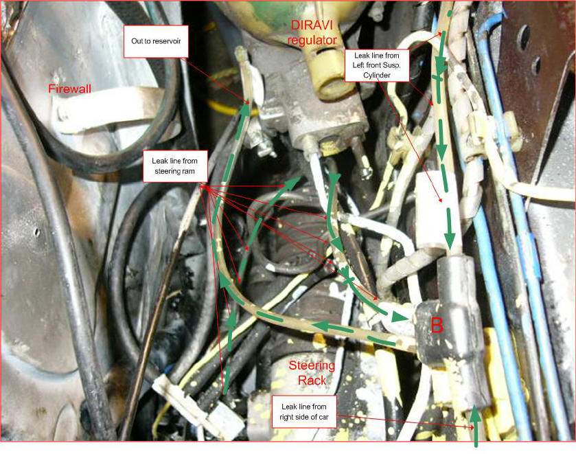 |
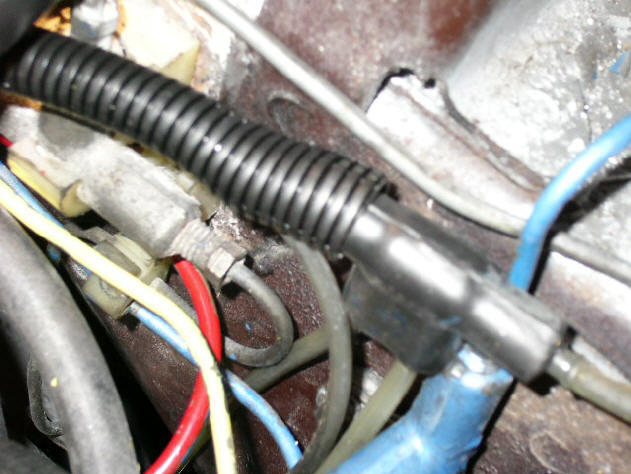
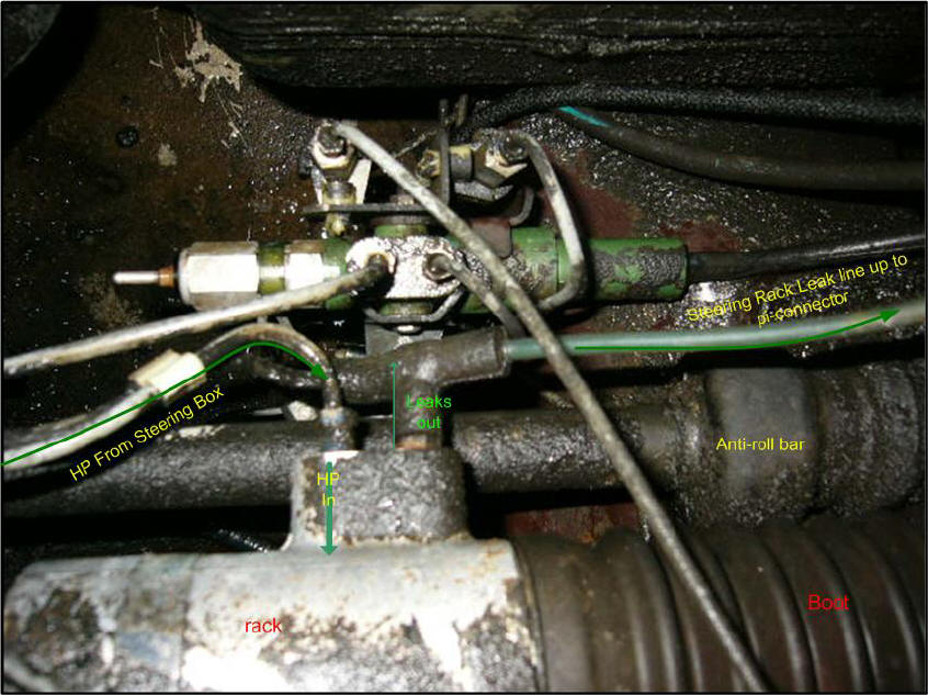
| Here is the leak line connection at the
left side of the steering rack. The connection is the black
rubber tee fitting. I have labeled just the steering items. This
image also includes the safety valve, the green tube with the steel HP
pipes screwed in. |
 |
| |
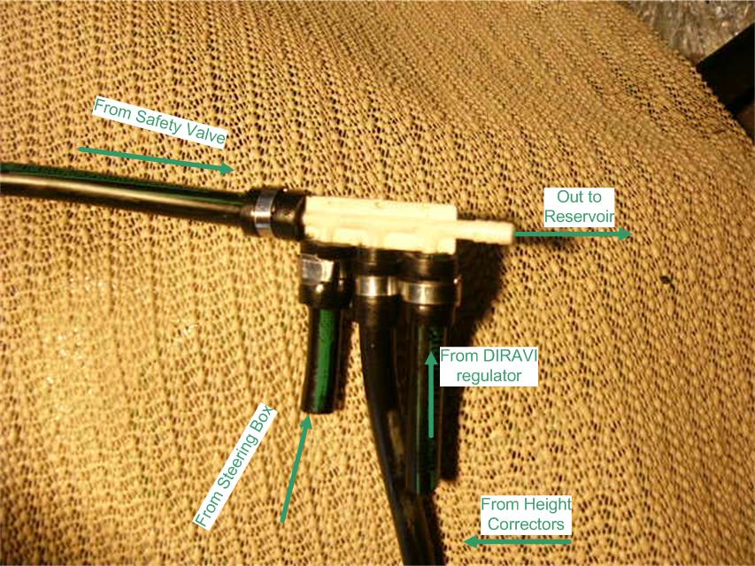
| The Spider leak line system |
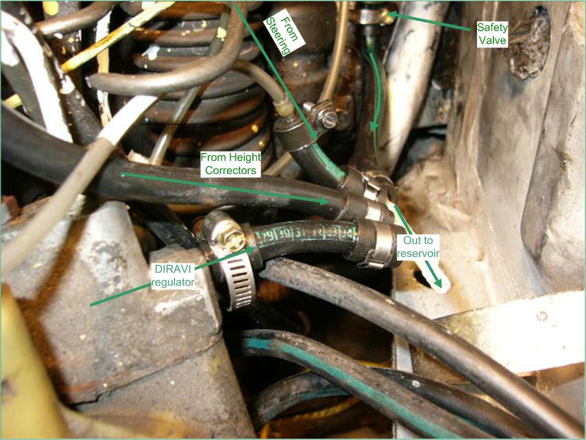
| The second leak collection system meets at a molded
hose fitting called a "spider." This system collects leaks from
the height correctors, a second line from the steering box, the DIRAVI
centrifugal regulator and the safety valve. |
| Here's my drawing of the system: |
 |
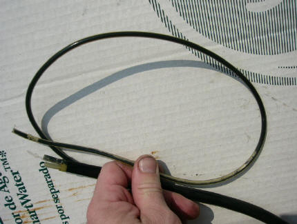
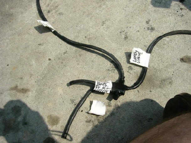
| The Spider is a set of Rilsan hoses
molded into a junction. Here is the spider I pulled from the
car. I had labeled the hoses. |
 |
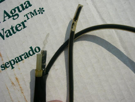
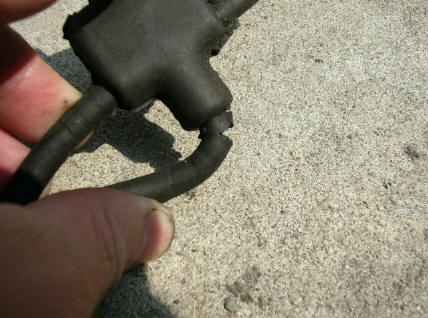
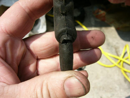
| The problem with the molded Rilsan
junction block is that the hoses narrow at the point of connection.
At this location they are weak. Over time, the hoses crack and
break, but only at the connection to the spider. The rest of the
hose is in good condition. I suspect the spider was designed for
installation in several different models, and for easy
installation at that. One mould could be set for this return system,
and millions could be churned out for installation in CXs, GSs, etc.
At the factory, the spider hoses would be connected at the appropriate
points, and the installation is complete. |
 |
 |
| |
| A replacement Rilsan spider is very
expensive, especially for a part that has a proven failure record.
So in this case I decided to fabricate something using a vacuum system
gang junction |
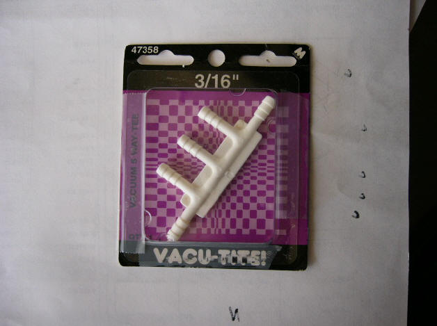 |
| lengths of Rilsan, and Ligarex. |
 |
 |
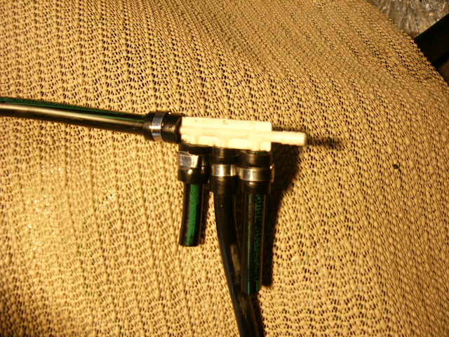
| Here are the systems that feed into the
spider. |
 |
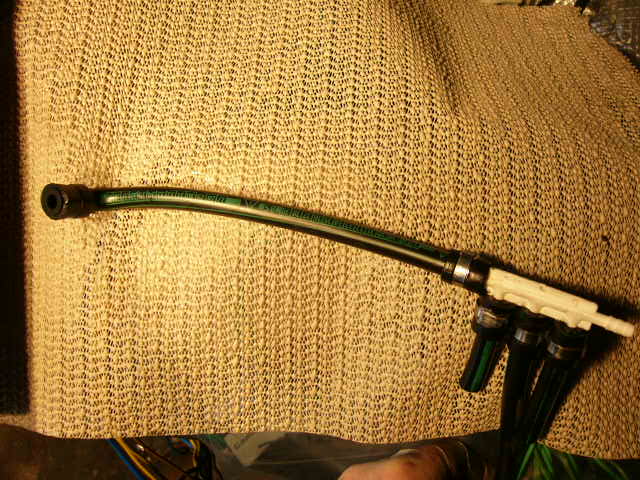
| The Spider replacement, as installed. |
 |
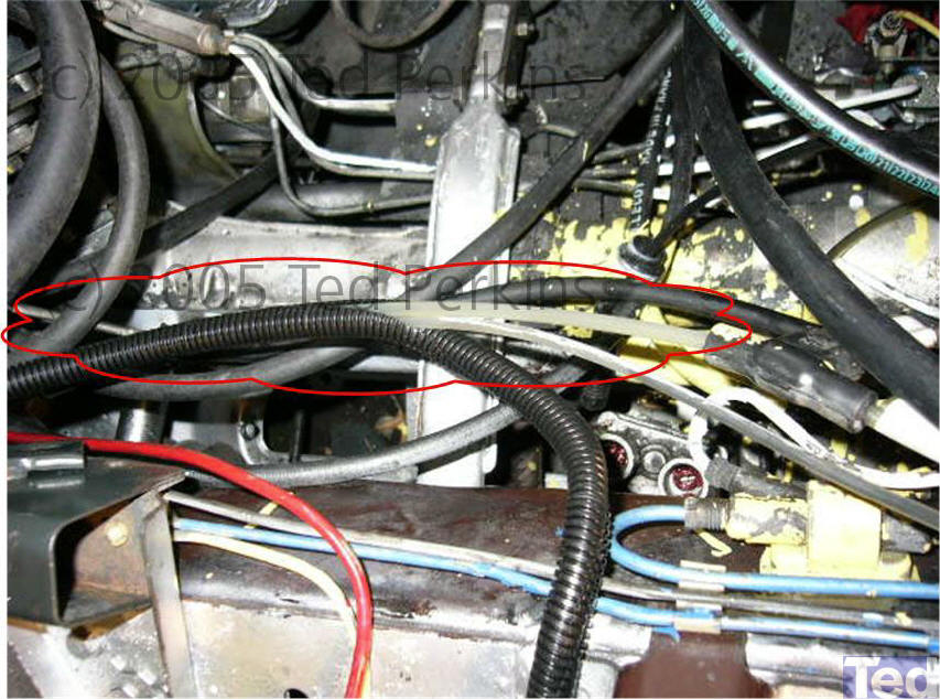
| I used split-loom conduit (the kind to
encase electric wires) to wrap and protect the leak lines |
 |
| |