| Even though I was able to consolidate a lot of fuses
and relays in the first Volvo fuse box, there still remained some
circuits that I wanted to control with relays. Specifically, the
lights (low beams, high beams and driving lights) and, if possible, a
relay that would take the accessory items off-line whilst the starter
motor was engaged. |
| I started with the main fuse box from a mid-nineties
Volvo 9-series. Volvo had this box near the battery with a set of
burly 50A (80A? I forget.) fuses. From the box, power was
distributed to other fuse boxes where the circuits were fused again.
Wow. Two fuses on a circuit. That's two more than Citroen
used on some circuits. |
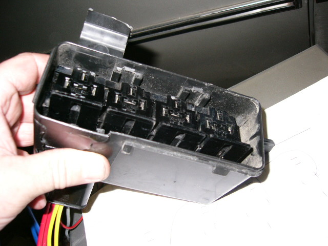
| Here's two views of the box, with the wires and fuses
about to be removed, and when I was test-fitting a way to hold the
relays in place. The reason I wanted to use this box is that I
could get it nice and watertight. |
here you can see the box, the fuses and the cover. when I was test fitting a way to anchor the relays in place.

here you can see the box, the fuses and the cover.
|
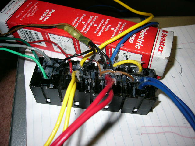
I used interlocking relay holders
 I found
at Waytek Wire.
I highly recommend them. I found
at Waytek Wire.
I highly recommend them. |
|
|
| Always, always, always, make a plan. I
sketched the locations of the relay terminals as they would look
from at the wire-side of the connectors. |
| A sharp eye will notice that I have 4 relays
sketched, but three blocks. The three blocks are for the lights,
which I wanted to wire up as a group. The fourth is for the
accessory circuit. The three light relays are sketched to the right.
|
|
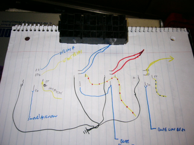 |
- The heavy blue, red and yellow lines at the top are for power to
the bulbs
- The line of yellow with red dots are to switch the relays for
the high and driving lights
- The line of yellow with blue dots is to switch the relay for the
low beam
- The two blue straight lines from the bottom are to feed power to
the relays, one to the low beam, one to the high beam, with a jumper
to the driving lights. Each supply wire has its own fuse in
the other relay/fuse box.
- The black line is to ground the relay switching circuits.
|
| For each wire that went in, I made a new sketch.
I drew ALL the relay pins, and then one line for the wire that was
installed. Kinda like a CAD drawing in layers, but on
paper. The relay pin diagram is the base diagram, and each wire
gets its own layer. I started with the jumper wires, since they were
short and I wanted to have enough working room as possible to put them
in. Then the heavier gauge supply wires, then the paired output
wires. |
|
The picture gallery below has
eight images. Use the little arrows to either side of the row of
small pictures to scroll through all of them. Click the image to
see a larger version. |
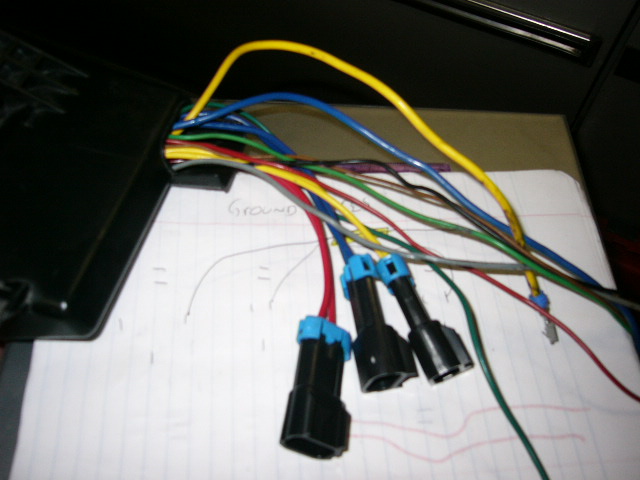
The brown switching wire for the high beam, with a brown jumper to the driving lights The blue power supply to the high beams with a yellow jumper wire to the driving lights Power to the low beam (yellow wire) wire to energise the low beam relay (red) When I made up the headlight wiring harness, I made these for connection to the relays. I made a loop, knowing I would Be cutting them to connect them to the relays Two yellow wires for the two low beams Two red wires for the high beams Two blue wires for the two driving lights

The brown switching wire for the high beam, with a brown jumper to the driving lights
|
| After I set up the power and switching circuits, I
made the ground wires. Relays don't pull very much power at all.
So, using smaller gauge wires is ok. |
|
There are six images in this
set, click on the little arrow at the right to see the last
image. |
Four wires, two long, two short, so they would all end at the center of the block cut back a little more insulation than usual twist them together. I guess I should have soldered them, but this seems to work. Put all four in a 10-gauge heat shrink butt splice. Connect to the outbound wire set of ground wires with relay terminals on on the four wires, a ring terminal on the single outbound wire Ground wires installed in block

Four wires, two long, two short, so they would all end at the center of the block
|
| pack the underside of the relay connections with
dielectric grease |
|
 |
| Feed the wires through the hole. One at a time
is easiest. |
|
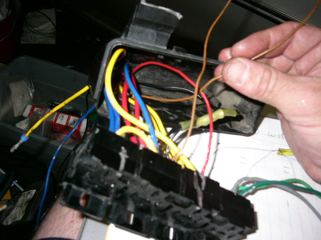 |
| The box with the wires pulled though, and the blocks
settled in place. I have to figure out a way to anchor them in
place. |
|
 |
| The wires from the hole at the bottom of the box.
I need to create some type of grommet at the base to make it
watertight. |
|
 |
| |


")
")


