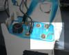
| Frankendash. I thought at first
that I would have to create something that was an amalgam of the
original dashboard display, and one that I found on ebay.
Once I dove into the project, I discovered that the original display
was in pretty good shape, and just needed a bit of a cleanup. |
| |
|
|
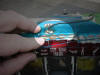
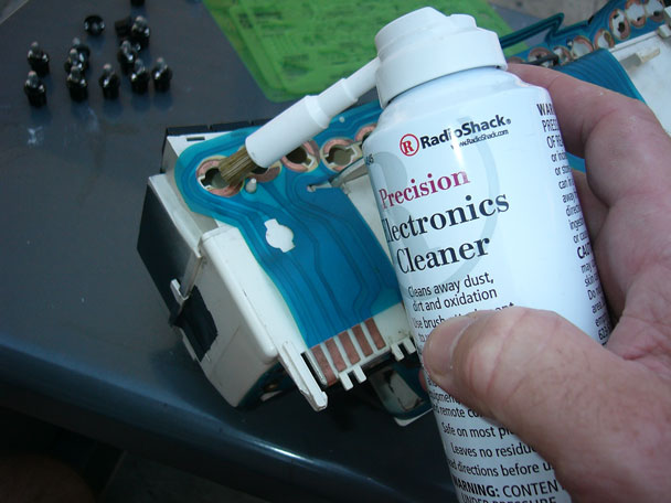
| I removed all the lightbulb holders and
cleaned the copper contact areas with electronics cleaner. The
pictured cleaner was a nice find. You just press the button a
bit to saturate the brush with the cleaning solvent, and you can then
scrub the contact area with the brush. It was certainly an
exercise in restraint - I needed to put enough pressure on the brush
to dislodge the dirt and corrosion, but I did not want to further
damage the printed circuit. |
|
 |
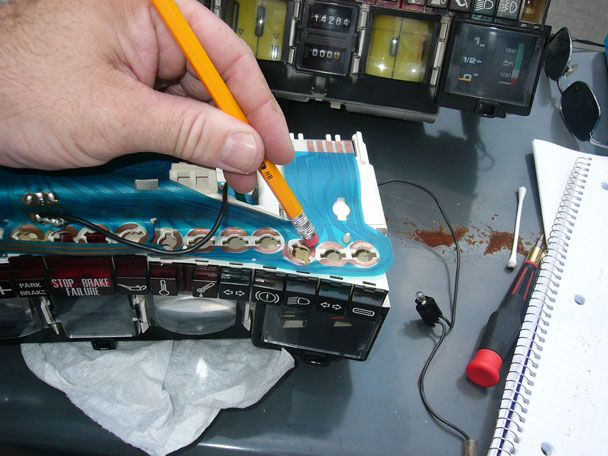
| After the first cleaning with the
electronics cleaner and brush, I went back with a pencil eraser to
polish the contact areas. The rubber of the eraser picks up the
oxidation from the copper, then you have to rub off the rubber that
has absorbed the oxidation. Patience is necessary - a few
strokes with the eraser on the contact, then a stroke or two on paper
or cloth to clean the oxidation off the eraser. |
|
 |
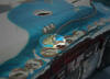
| The exposed copper strips look a little
better. I hope the electrons find them more attractive. |
|
|
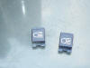
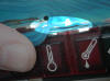
| Replacement of some lenses. The
white paint for some of the lenses for the warning lights was
scratched, so I took the corresponding lenses from the donor dash. |
|
|
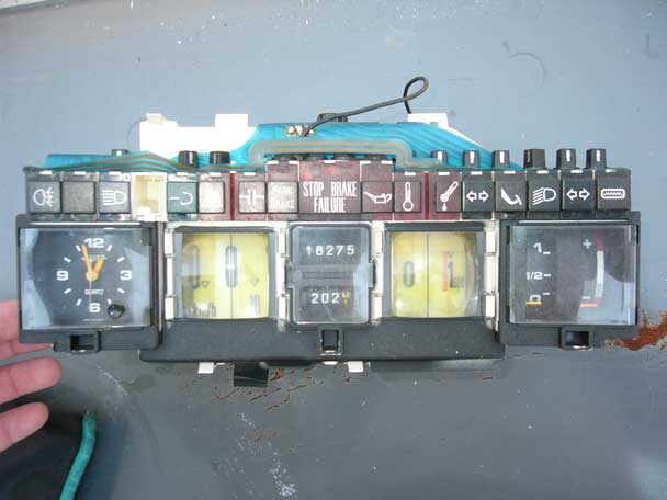
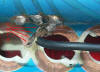
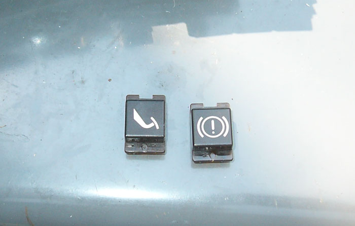
| The Australian Design Regulations (ADR) version of the
CX has an ambiguous pedal for the brake pad wear indicator. The
Italian version has the more interesting 'Your brakes are fucked!'
design. It went on the car. |
|
 |
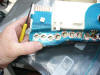
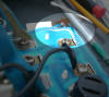
| The printed circuit was damaged in
several areas. There were several instances of the copper
strip separating from the plastic. This usually occurred where
the film was bent. |
| On the rear of the display.
Rightmost image is after the repair. |
|
|
| |
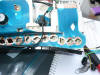
| Two copper strips have separated here. |
|
|
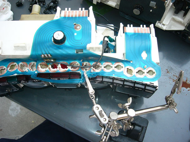
| Repairing the separated copper strip.
I held the strip in place with the little clampy thing (the best $10 I
ever spent at radio shack) and dabbed the area with silicone
sealant/adhesive. Just the generic stuff you can find at a home
improvement store or a car parts store. Rightmost image is after the
repair. |
|
|
| Another area where I pasted the copper
strips into place with some silicone. |
|
 |
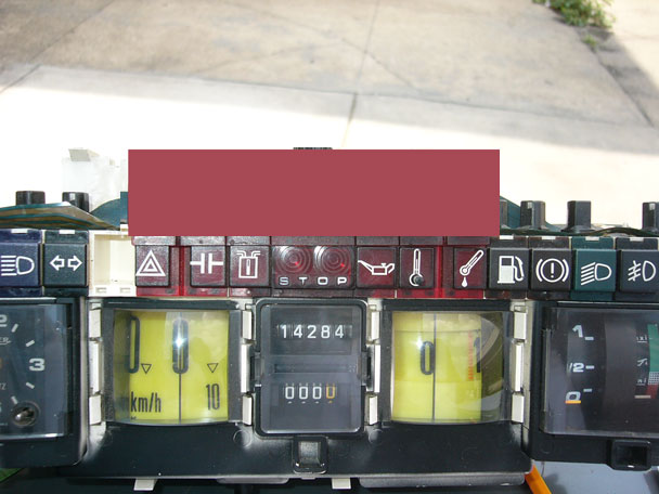
Now, the real mess. The STOP lens
is illuminated by two bulbs. The OEM version had a arrangement
that would illuminate STOP concurrently with the illumination of
lights for:
- HP Failure
- Loss of Oil Pressure
- High Water Temperature
|
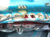
| First, a photo of an OEM dash (the one
from italy via Ebay) (you'll see why I inserted the
shaded box in a moment) |
|
 |
| |
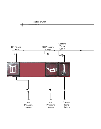
| My homemade circuit diagrammes: |
| Closure of HP pressure, Oil pressure or Coolant temp
switch will illuminate the respective light. |
The STOP light is an overlay on these circuits,
connected via diodes. Closing a switch lights the warning and STOP
lamps. Each circuit is isolated via a diode. |
 |
 |
From what I can decipher, ADRs required:
- A lamp to show the parking brake is engaged
- The light indicating brake failure (HP loss) should flash.
- Indication that the level in the LHM reservoir had dropped.
(this was added to later versions of the CX, but early
versions of the CX only warned of a loss of HP - no circuit for the
reservoir.)
|
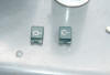
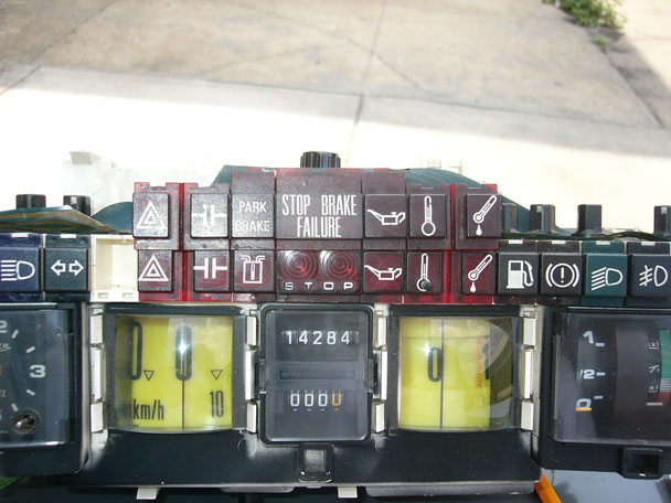
| Here's the ADR-spec set of lenses,
resting on the OEM display: |
|
 |
|
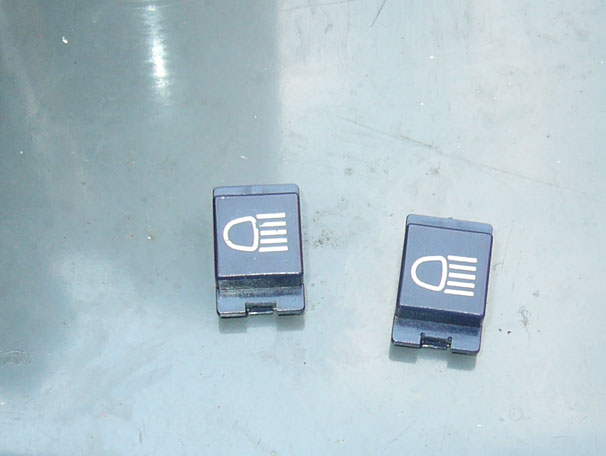
The HP loss light, |
|
 |
|
was replaced with "PARK BRAKE" |
|
and S T O P was replaced with "STOP BRAKE FAILURE" |
|
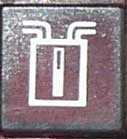
(the lamp of two plungers pushing
together warns of torque converter overheating, not an issue for a
manual transmission car) |
|
The lamp test button ( in the centre of the coolant
temp lamp) was deleted. |
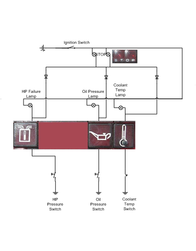
| My homemade drawing of the circuits: |
|
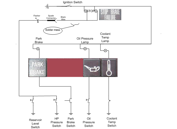 |
- The diodes bridging STOP to the warning lights were removed.
- The LHM reservoir lens was replaced with "PARK BRAKE".
That lamp's connector was wired to the switch on the handbrake.
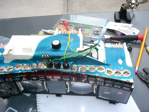
- A glob of solder was put on the printed circuit, and a black
wire was put into place. The black wire went to a flasher, which was
connected to the circuits for the HP pressure and LHM reservoir.
This limited the information conveyed by STOP to just a failure on
the HP system. Circuit closures on the oil pressure and
coolant temperature switches would not illuminate the STOP light.
|
| |
| The problem is that the film is torn
right at the blob of solder. I suspect the heat of the soldering
operation weakened the film. |
|
|
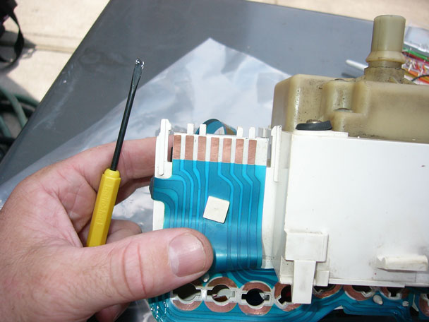
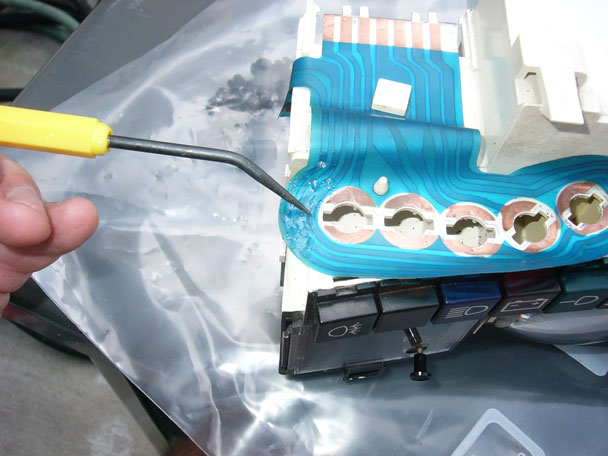
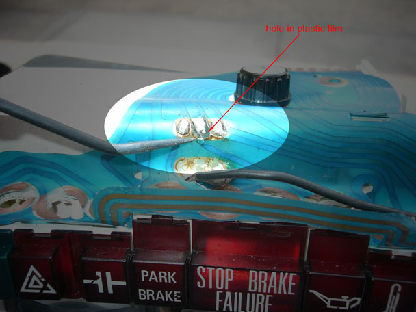
| The damage from the solder is not just at
the connection for the STOP light. The circuit for the oil
pressure light was also damaged. The heat from the solder melted
a hole in the plastic film. The connection for the oil pressure
light circuit is though the little bit of solder that I'm pointing at
from the left with a needle. |
|
 |
| |
| |
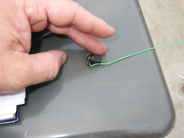
| What little electrical continuity the
copper might provide these circuits is probably next-to-nothing by
now. I bought a box of little breadboard jumper wires & managed
to wedge the wire into the bulb holder. |
|
 |
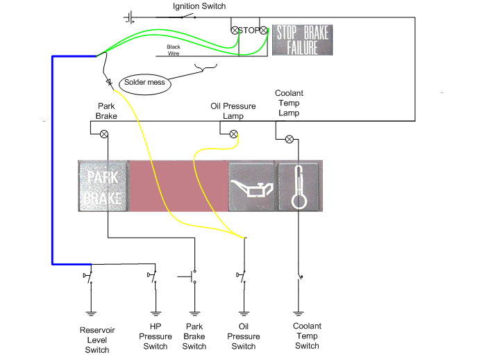
Conceptual of my fix.
- Brand new wire (BLUE) from the LHM
reservoir & pressure switch to the dashboard.
- The flasher is removed from the circuit. Too many chances
of a circuit break on an important warning light.
- Jumper wire (GREEN) directly from
the STOP bulb holder to the blue wire. Molded OEM connector
and printed circuit is bypassed.
- Jumper wire (YELLOW) from oil
pressure bulb holder to oil pressure light. Molded OEM
connector and printed circuit is bypassed.
- Jumper wire (YELLOW) from STOP
green wires to oil pressure wire connector. This will light up
STOP if oil pressure is low.
- Diode in yellow jumper wire listed #5 above. This prevents
the oil pressure lamp from lighting if the LHM reservoir or HP
switch closes.
|
|
 |
| |
| I rigged up a little harness of two bulbs
for the STOP light (green wires) and one bulb for the oil pressure
light (yellow wires). |
|
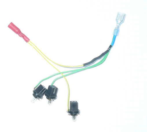 |
| The bypass harness, as installed. |
|
 |
| |
| |
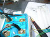
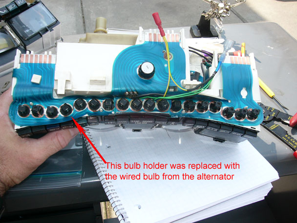
| The OEM charging system was a complete
mess, so I tore it all out, including replacing the fragile
Paris-Rhone alternator & external mechanical(!) voltage regulator with
a robust Delco 95A internally regulated alternator. The Delco
alt has a provision to light a charging indicator on the dash when the
exciter circuit is active. The OEM dash has a thermal voltmeter,
but that's not enough. The later versions of the CX did have a
charging indicator lamp, so I chose to retrofit this change back
to this car. The donor dashboard had a lens and a special light
holder for it. Evidently Citroen saw fit to add the light, but
just piled the extra circuit on top, instead of re-engineering the
printed circuit. The entire car's electrical system was designed
this way. Instead of modifying the original circuit design
to accommodate a change, they kept the original wiring design, and
just added another circuit on top. The ring connector gets Hot+ from
the ignition switch, the plastic sleeve connects through to the
alternator. |
|
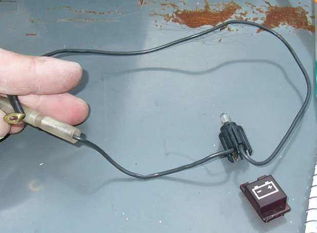 |
| I took this picture before I put back the
wired bulb for the charging system. |
|
 |
| |
| |
| |