|
|
|||||||||||||||||||||||||||||||||||||||||||||||||||||||||||||||||||||||||||||||||||||||||
|
|
|||||||||||||||||||||||||||||||||||||||||||||||||||||||||||||||||||||||||||||||||||||||||
| Along with the Cooling System, parts of the
air conditioner came out. I plan to replace everything but the
evaporator core, which is too buried between the dashboard and
firewall to be worth the effort. The system on the car has the
ancient flare fittings. I plan to yank everything that can be
replaced with o-ring fittings. I will research the market offerings
for an a/c evaporator that rests in the trunk & provides supplemental
cooling.
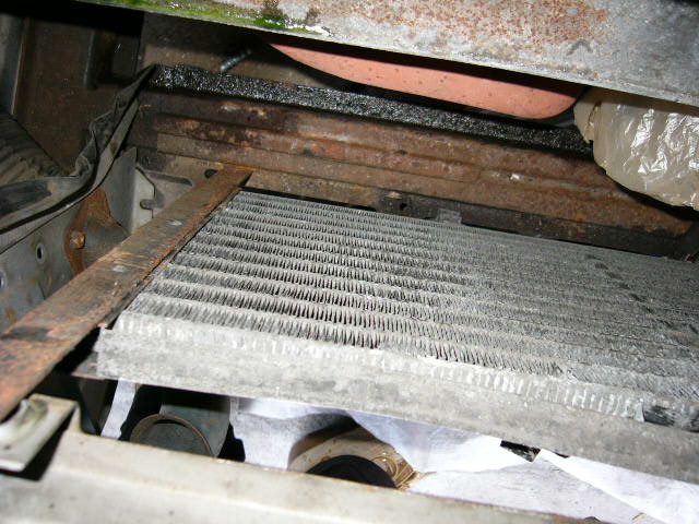
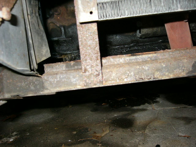
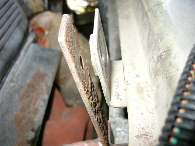
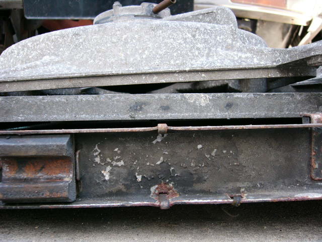
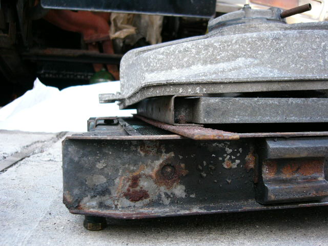
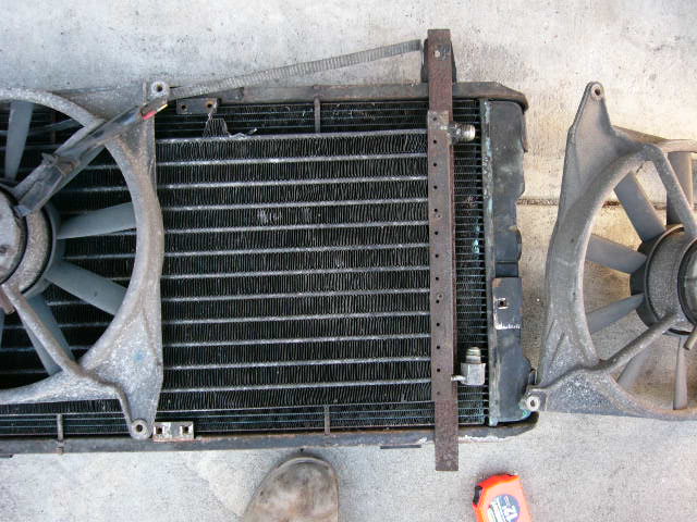
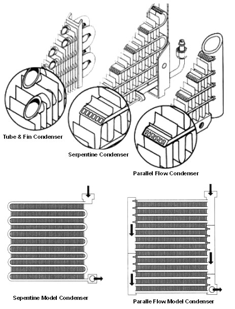
Condenser: Will be replaced with a parallel flow condensor The original condenser measured 23" by 12", with some room to spare on all sides. the original was a better design than what I expected to find. The condenser is mounted on two vertical slats which rest on the radiator crosspiece
and are bolted to the car at the upper radiator mounts
I'll probably have to fabricate a new mounting system for the replacement condensor. The heavy aluminum frames for the electric fans are bolted to the radiator, sandwiching the condenser into place.
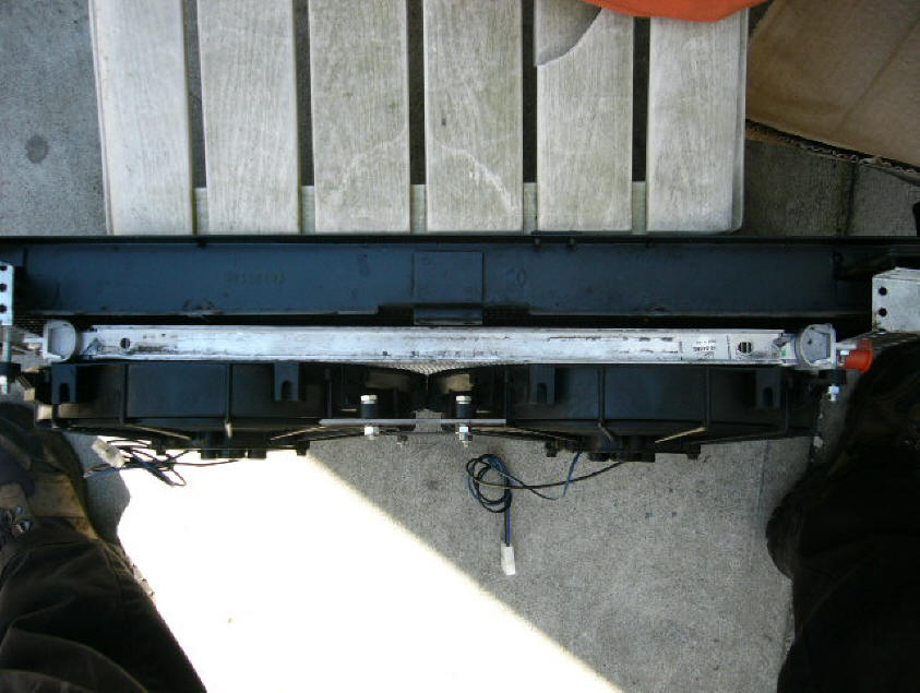
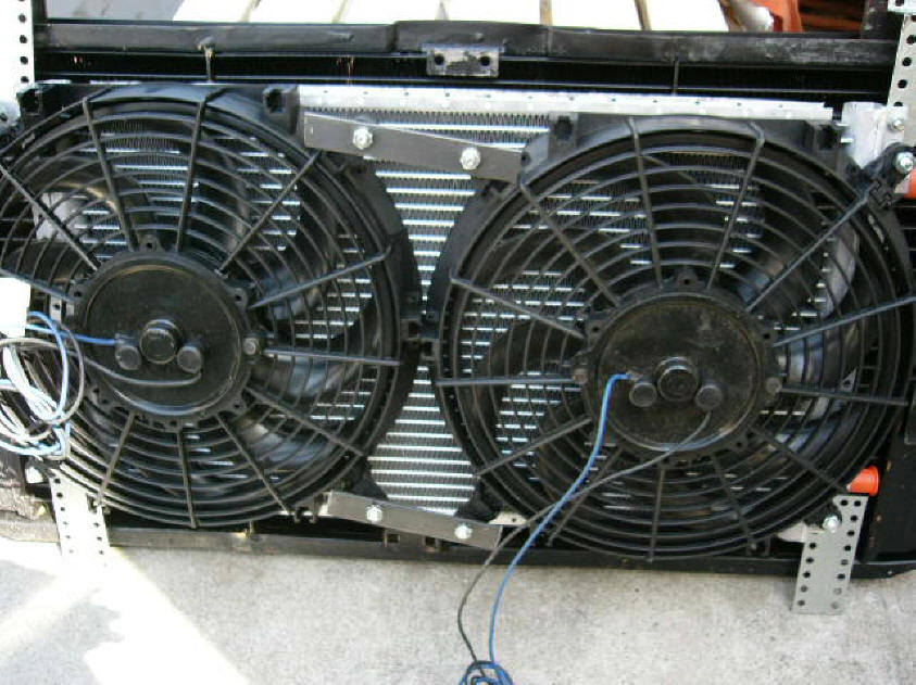
Here's what will go in the car:
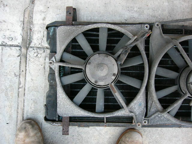
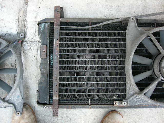
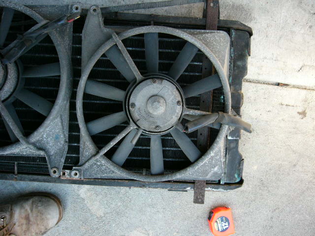
I had the radiator recored by a shop over in Jamaica. The condensor and the fans came with a nice assortment of mounting hardware. I use the flat metal plates with holes to anchor the fans to the condensor. The fans are pretty light - the frames are plastic - and most of the weight is borne by the two legs that I fabricated. The upper flap plates will get sandwiched between the radiator and the chassis crossmember. I'm not too worried about torsional stress on the condensor.
Compressor: Current installation has a Sankyo/Sanden 508 compressor, with a 2-belt pulley. The ports are on the end of the compressor. Although in good shape, it might get replaced with a new Sanden compressor. The one in the car now is a 5-cylinder rotary. The replacement compressor is a new Sanden 508 7-cylinder compressor, manufactured to handle R134a. Hose: Everything gets replaced.
New R134a hose set installed. Ordered from Classic Auto Air. 1813 251 2356 Fittings: The new system will have crimped O-ring fittings everywhere, except for at the evaporator. I do not want to pull it out.. Rear Evaporator unit: Hurricane sells an evaporator unit designed to hang from the package shelf behind the passenger seat. I plan to install one in the car. I have to figure the hose routing first. I also need to study the pros & cons of flexible hoses (which are bulky) and rigid aluminum tubes which are more difficult to install, but are more compact. I estimate about 20' of material to run from the engine compartment to the trunk. March 19: I want to revamp the front end A/C system first to see how it copes with the heat. If it is not sufficient, I will add the rear a/c system. The rear system is actually an easier and cleaner installation than I had anticipated. I will design the connections at the firewall to accommodate t-splicers.
Fans The existing fans have a reputation for bearing failure. Since they are out, they will be replaced. The 1977 design used heavy aluminum frames to hold the fans and sandwich the condenser to the radiator. In 1987, the fans had plastic frames. The new fans appear to be much lighter in construction, and do not block as much airflow through to the radiator. I think the replacement assembly will have the condenser mounted directly to the radiator, and then the fans will just be attached somewhere on the package. I do not want to use the fan frames as structural members to hold things together. The factory fans have a swept diameter of 12", and were 5" deep. The radiator core is 14x 26. I will swap out the blower motor as well. Here are my drawings of the Air Conditioner electrical system;
Here is a drawing prepared by RTA. What's different between my design and the RTA version?
|
|||||||||||||||||||||||||||||||||||||||||||||||||||||||||||||||||||||||||||||||||||||||||
Parts:
|
|||||||||||||||||||||||||||||||||||||||||||||||||||||||||||||||||||||||||||||||||||||||||